This is a course project for ME3224-Manufacturing Process, guided by Prof. Jingyu Pei A machining process plan has been developed, embracing the concept of iterative design.
1. Mechanical Part Selection
1.1 Introduction to Part Working Conditions
The part selected is the right thigh mechanism (Figure 1.1). Its primary function is to facilitate jumping movements, achieved by the rapid return action of the cam and the torque of the torsion spring (Figure 1.2). For detailed explanations, please refer to a separate post.
- Hole C is connected to the torso via Axis 5.
- The rollers on the shafts of Holes A and B bear the output of Cam 3, driving the motion of the thigh mechanism.
- Hole D connects the thigh to the lower leg 7 via an axis.
- The remaining holes in the thigh mechanism are used to secure one end of the torsion spring. During operation, the parts experience reciprocating motion, leading to complex alternating stresses, which can cause fatigue damage. Therefore, the parts require high stiffness and strength, wear-resistant surfaces, and meet stringent precision requirements.
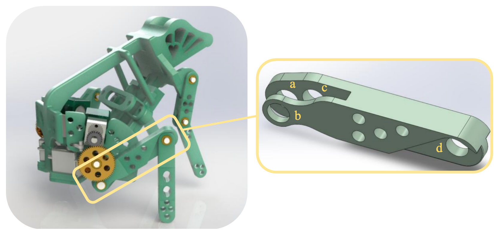
Figure 1.1: Overall Structure and Parts Selection
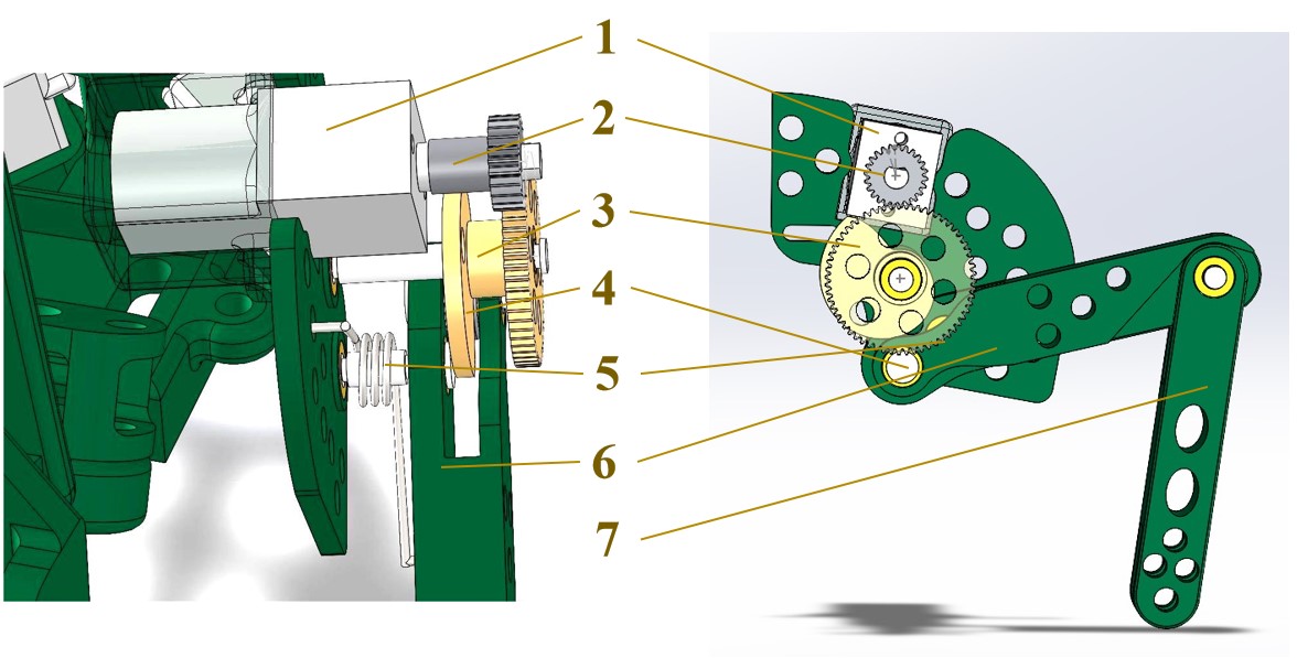
Figure 1.2: Related Parts Layout
1 - Motor; 2 - First gear; 3 - Second gear and cam; 4 - Roller; 5 - Thigh shaft; 6 - Thigh; 7 - Lower leg
1.2 Original Part Drawing
The original drawing is depicted in Figure 1.3. To facilitate the machining process design, the part is enlarged fourfold in subsequent analyses.
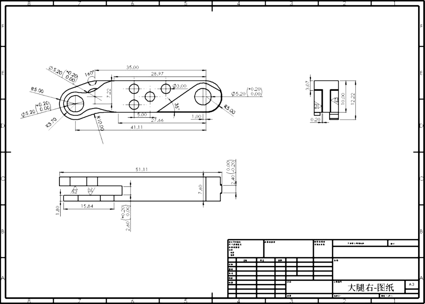
Figure 1.3: Original Drawing of Thigh Part
2. Improvement of Part Structural Processability
2.1 Overview of the Improved Part
In line with the requirements for structural manufacturability, the part has been improved, with the overall outcome displayed in Figure 2.1. Subsequently, a breakdown analysis of the part’s iterative design is conducted.
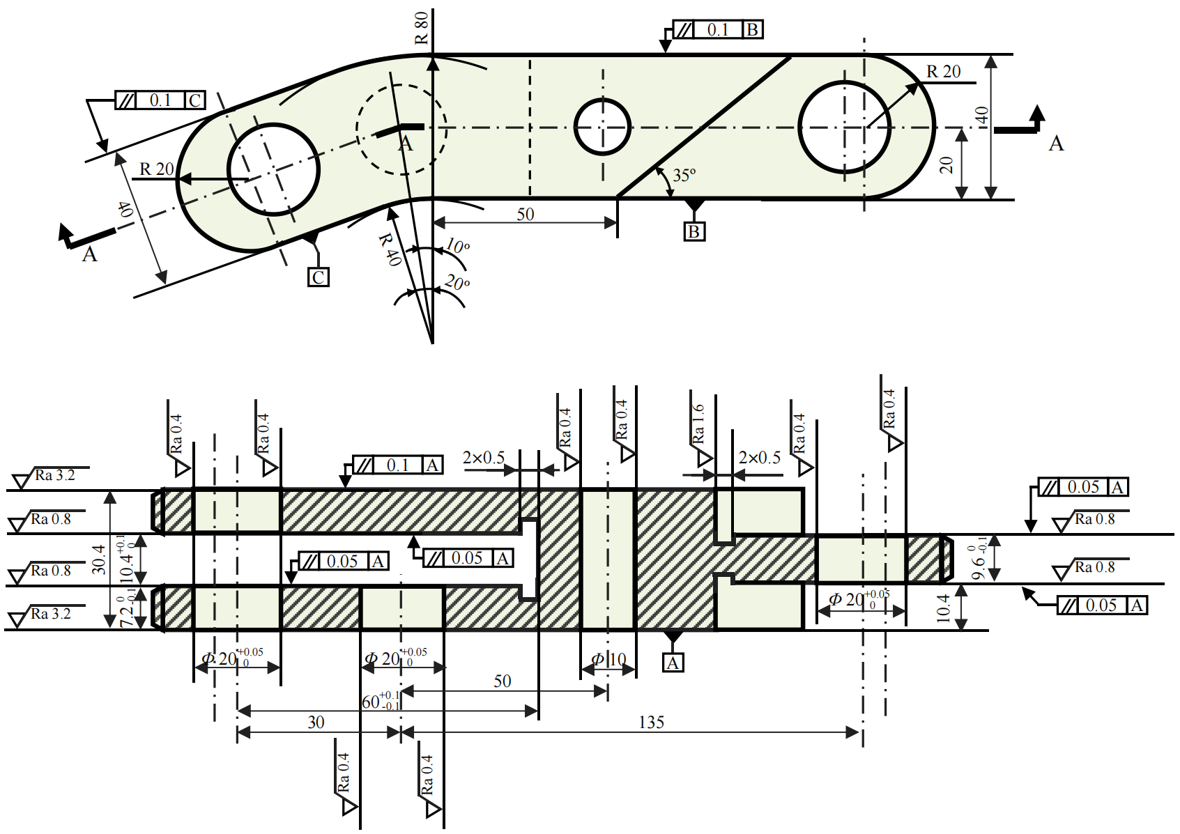
Figure 2.1: Overview of the Improved Part
2.2 Dimensional Tolerance Setting
Figure 2.2 highlights the critical dimensions that require higher precision in red.
- Except for the φ10 hole, which is used to pass the torsion spring and has lower precision requirements, all φ20 holes are designed to mate with shafts and thus demand stringent precision.
- The left slot, which is the spatial domain for cam rotation, necessitates precise dimensions for length (60mm) and width (10.4mm).
- The inner thickness (7.2mm) must align well with the shaft and bearings, hence it also requires precise specifications.
- The thickness of the far-right plane (9.6mm) is related to the fitting with the lower leg part and thus necessitates precise accuracy.
These precision settings correspond to the part’s requirements. For an analysis of whether these can be achieved in machining, refer to the dimensional chain analysis in Section 5.
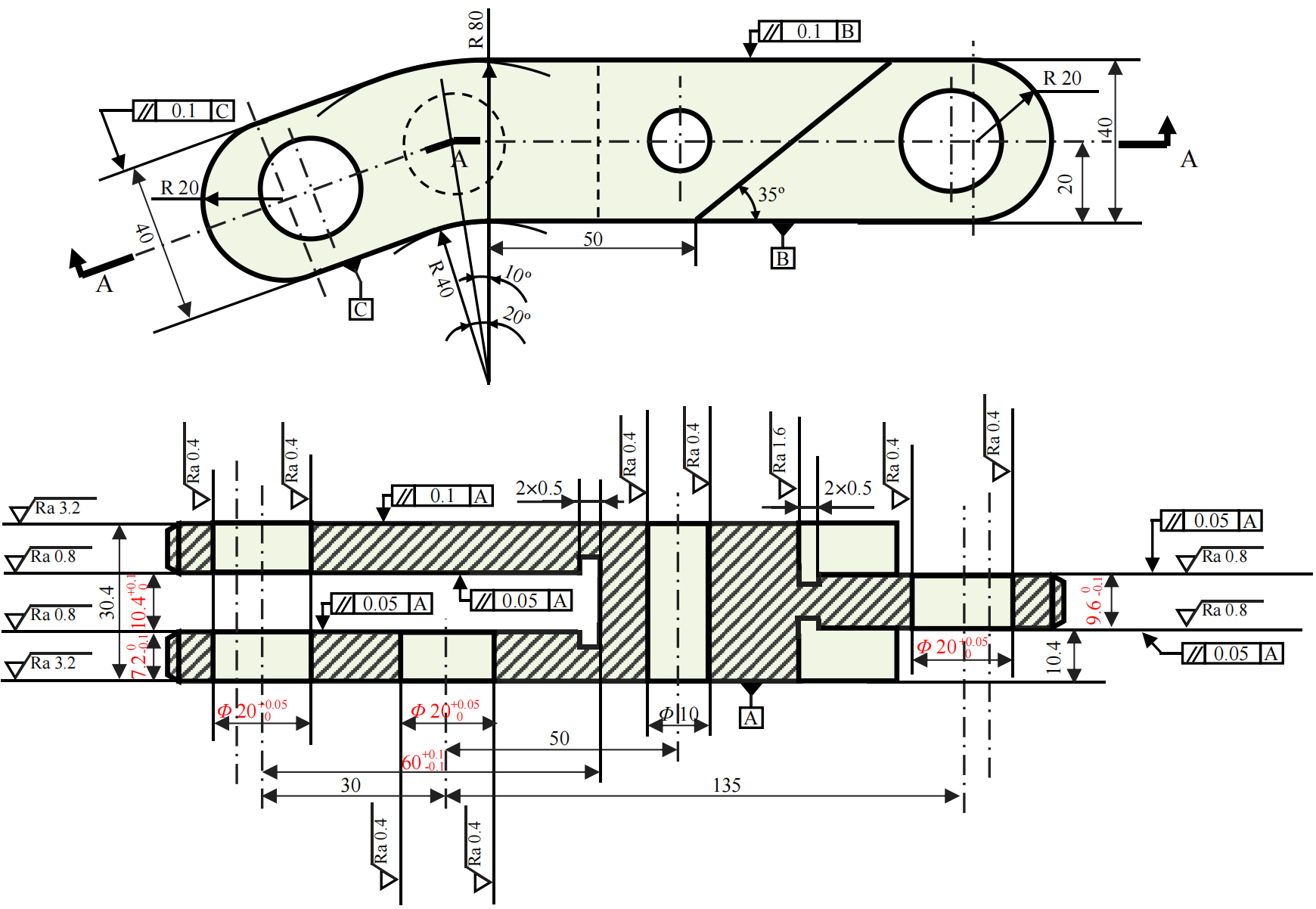
Figure 2.2: Dimensional Tolerance Setting
2.3 Position Accuracy Setting
The parallelism requirements, indicated in blue in Figure 2.3, are associated with:
- The slot on the left that accommodates the cam.
- The face on the right that interfaces with the lower leg part.
- The parallelism requirements related to planes B and C, which are primarily to ensure the overall flatness and symmetry of the part.
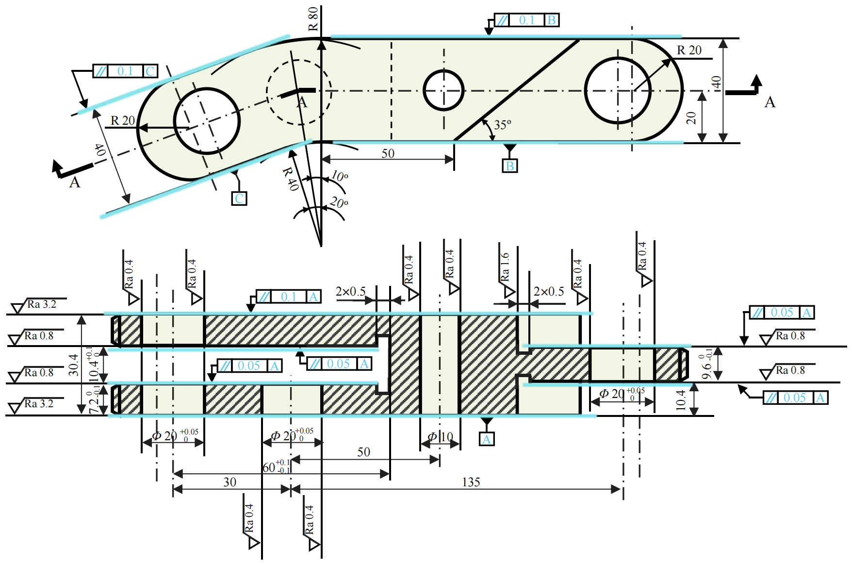
Figure 2.3: Position Accuracy Setting
2.4 Chamfer Setting
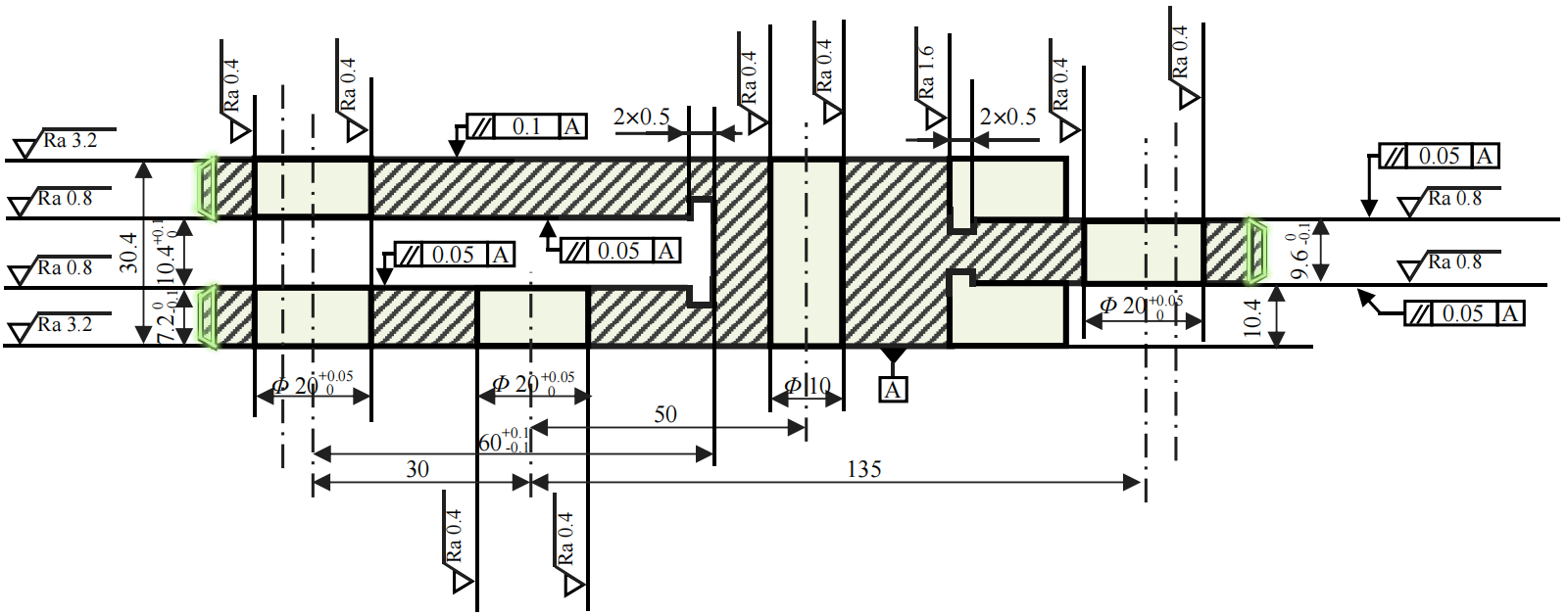
Figure 2.4: Chamfer Setting
2.5 Surface Roughness and Backing Groove Setting
- Each hole, which must mate with shafts and other components, requires a high degree of surface roughness (Figure 2.5).
- When the entire part is subjected to stress, it may shift, causing the left slot to come into contact with the cam plane. Therefore, the left slot plane requires a certain level of surface roughness to ensure normal rotation of the cam.
- The far-right plane, which is in contact with the lower leg part’s plane, also necessitates a certain level of surface roughness to ensure it does not affect the lower leg part’s rotation around its axis (Figure 2.6).
- To meet surface roughness requirements, grinding processes are necessary, hence backing grooves are set to prevent potential damage to end faces by grinding tools.
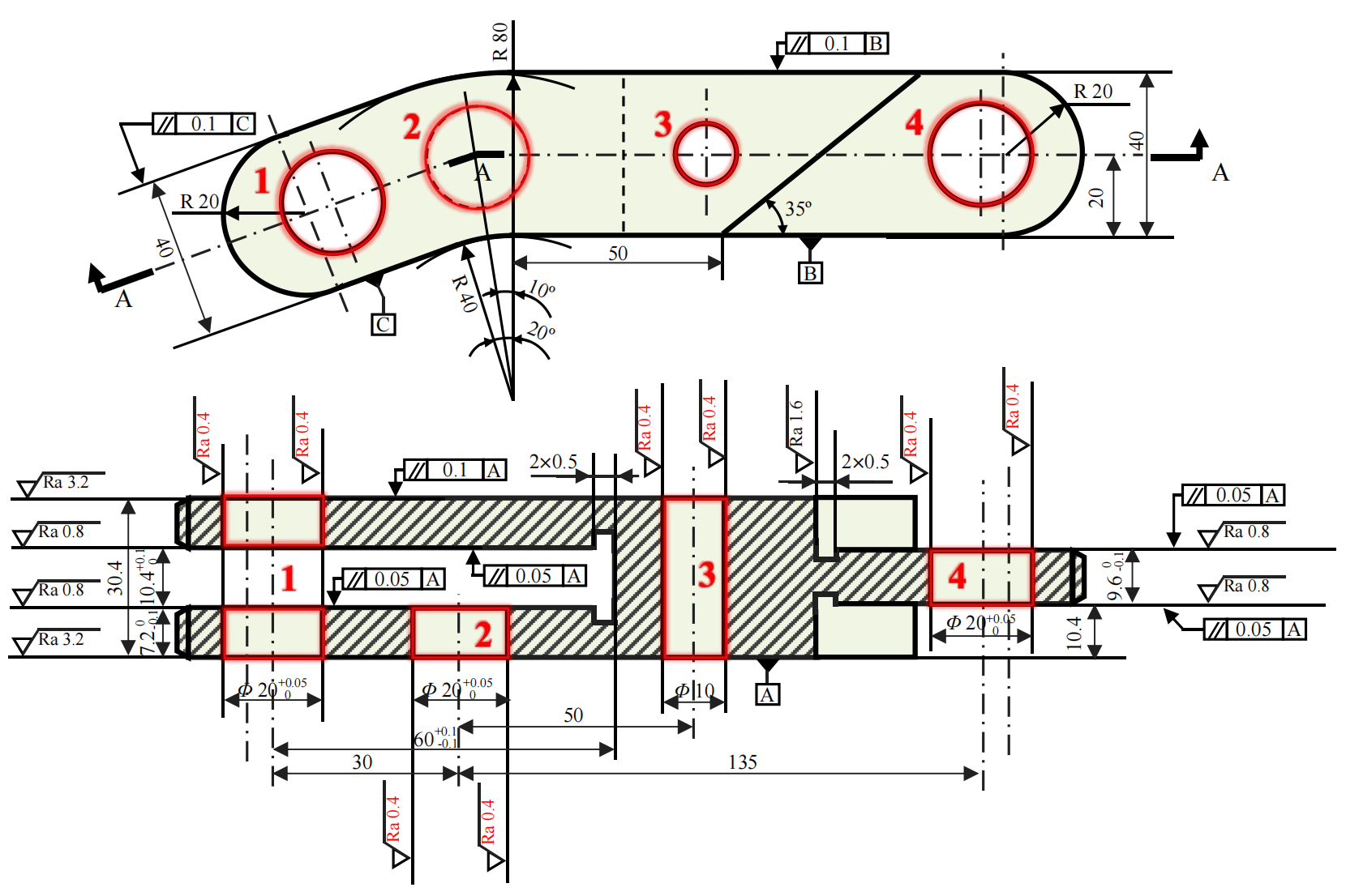
Figure 2.5: Hole Roughness Setting
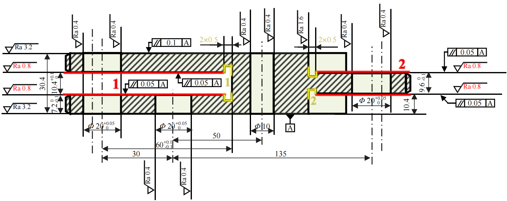
Figure 2.6: Plane roughness and Backing Groove Setting
3. Materials, Blank and Heat Treatment
20CrMnTi carburized steel is selected. After carburizing and quenching, the surface exhibits high hardness and wear resistance, while the core maintains high strength and toughness, and it has good machinability after normalization. This material is commonly used for manufacturing important parts with a cross-sectional area of less than 30mm that are subjected to high speed, medium or heavy loads, impact, and friction.
The blank is chosen as a forging. After forging, the surface forms a streamline distribution of fiber organization, and the internal structure is compact and uniform, effectively enhancing the mechanical properties of the part. Model forging is adopted to meet the requirements of mass production.
4. Machining Process Procedure
4.1 Procedure Chart
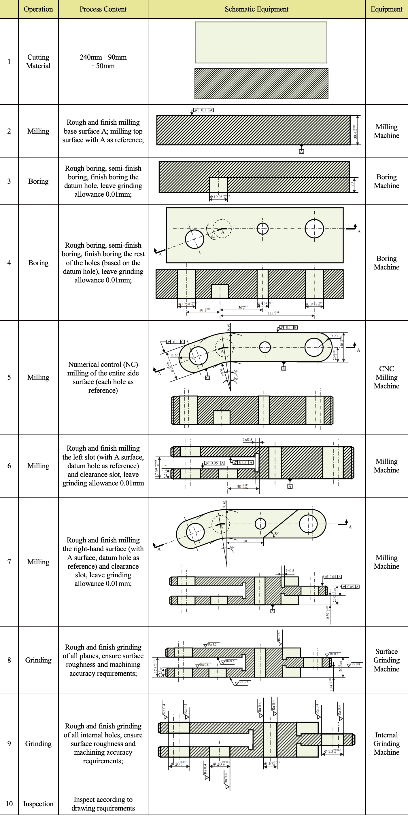
Following the principles of prioritizing main tasks, starting with rough machining before fine machining, establishing the base surface first, and machining surfaces before holes, the process procedures for mass production are designed as shown in Table 4.1.2. Notes:
- Since the entire side is an irregular surface combination of plane surfaces, it is difficult to use as a reference for machining other surfaces and holes. On the other hand, many dimensions of the entire part are related to Hole 2 (Figure 2.4) for connecting with body parts. Therefore, this hole is processed first as a precision reference. The reference for other holes is also this hole. The side is subjected to numerical milling with each hole serving as a reference, hence the hole processing precedes the side.
- The dimensional tolerance for each machining step is determined according to the tolerance levels of fine milling IT7 and fine boring IT6 (Table 4.1).
Table 4.1: Standard Tolerance
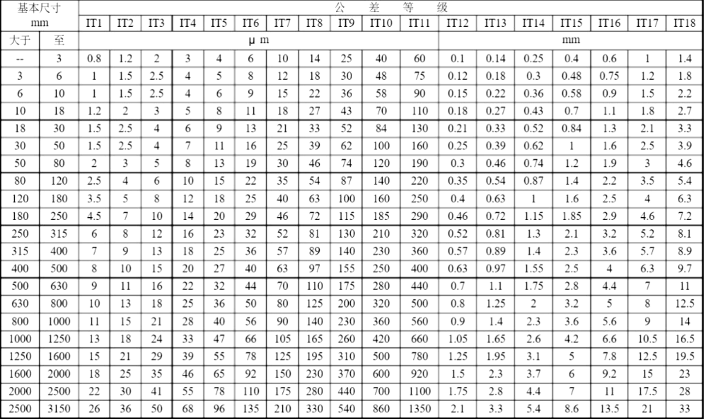
Table 4.2: Machining Process Plan
5. Dimension Chain Calculation: Accuracy Inspection
5.1 Inner Hole Sizes
Each hole is directly machined, and the comparison of processing requirements and processing process precision is shown in Figure 5.1, which meets the requirements.
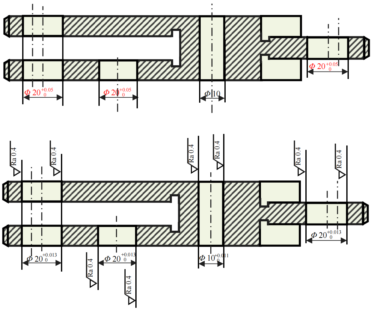
Figure 5.1: Hole Accuracy Inspection: Comparison of Machining Requirements and Process Accuracy
5.2 Plane Related Dimensions
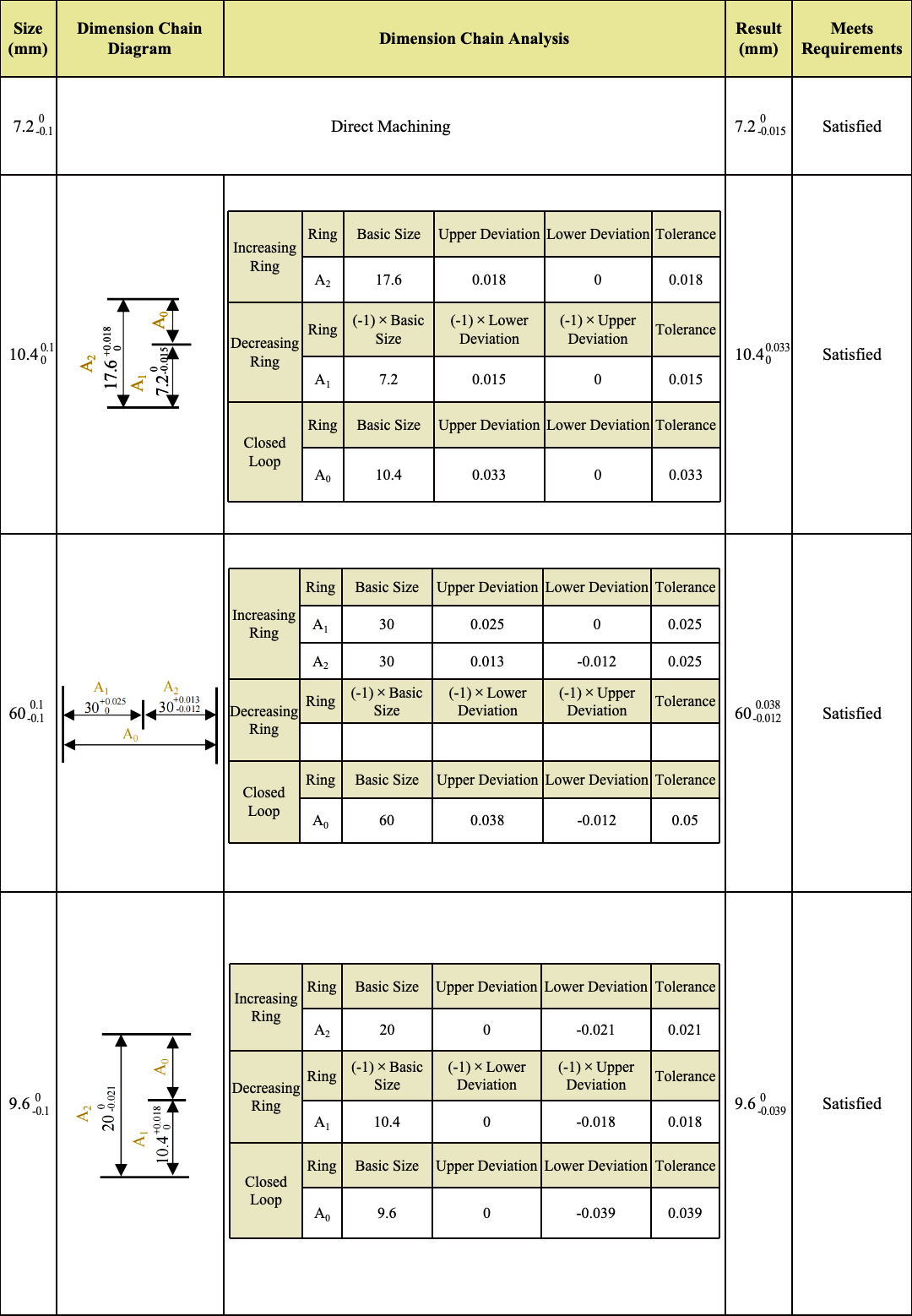
The dimensional chain analysis for important dimensions is shown in Table 5.1, which meets the requirements.
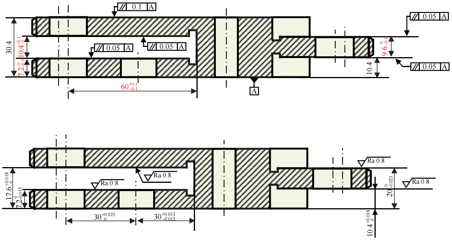
Figure 5.2: Plane Accuracy Inspection: Comparison of Machining Requirements and Process Accuracy
Table 5.1: Dimensional Chain Analysis