This is a course project of ME3220-Design and Manufacture II guided by Prof.Xinjun Sheng. We designed a frog-like amphibious robot, carrying out mechanical design, circuit design, prototype production and so on.
1.Background Research
Contributor: Yuchen Yang, Zhenglei Li
1.1 Comparison of Similar Robots
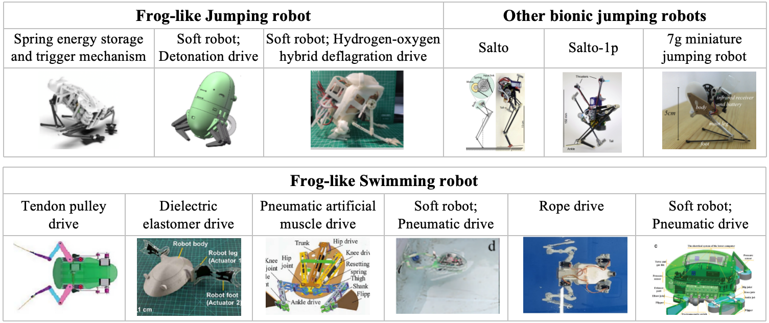
Frogs, with their exceptional jumping and swimming capabilities, serve as excellent models for designing robots with similar functionalities. Our aim was to design a frog-like amphibious robot capable of both jumping and swimming, using a mechanism that is both efficient and adaptable. We began by investigating various existing biomimetic robots with jumping and swimming functions to identify potential design solutions (Table 1.1).
Table 1.1: Typical frog-like jumping/swimming robots
1.2 Principle analysis
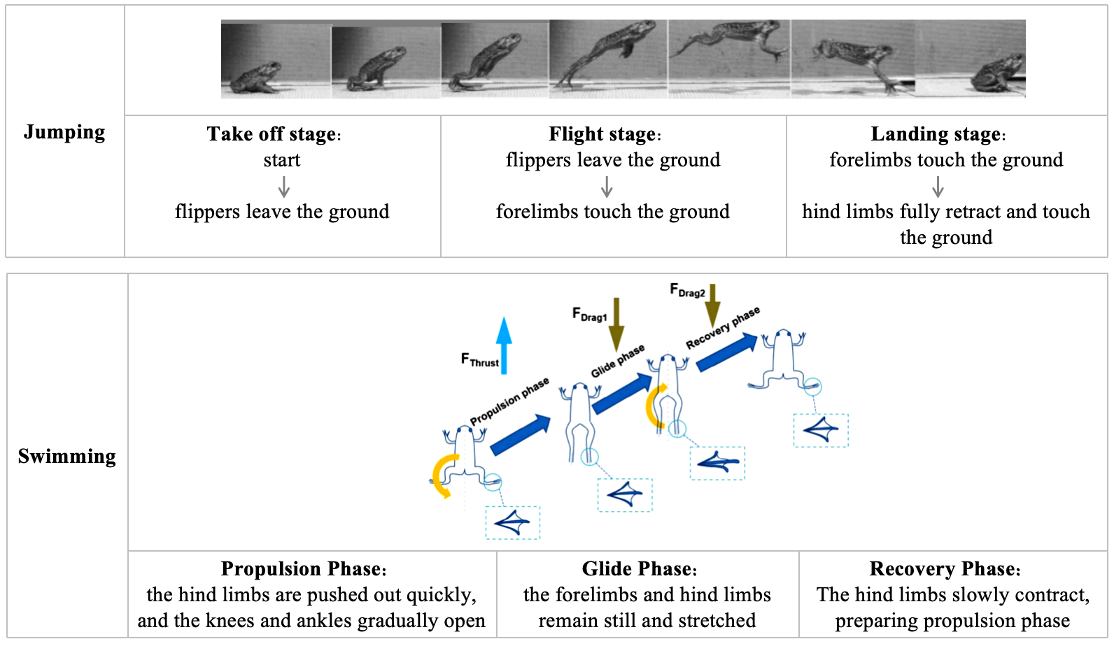
We conducted a detailed analysis of the different stages of frog jumping and swimming (Table 1.2). The jumping mechanism in frogs involves a slow buildup of energy followed by a rapid release, whereas swimming is a more continuous motion. To replicate these behaviors, the robot’s energy storage and release system needed to be both powerful and sustainable. Considering the above technical requirements, we choose the cam and torsion spring to realize the energy storage and release function.
Table 1.2: Frog Jumping/Swimming Stage Analysis
2. Functional Decomposition and Mechanism Design
Contributor: Yuchen Yang, Yiqin Ma
2.1 Overall Architecture
Using SolidWorks, we performed 3D modeling to design and assemble the various components. The overall architecture is outlined in Figure 2.1:
- Torso: Houses electronic control components and integrates various functional modules, considering size and biomimetic requirements.
- Forelimbs: Equipped with torsion springs on the joints for posture maintenance, adjustment, and cushioning during the jumping process.
- Energy Storage and Hind Limbs Unit: A key module for implementing jumping and swimming actions.
- Amphibious Mode Switching Unit: A key module for switching between the jumping and swimming modes of the amphibious robot.
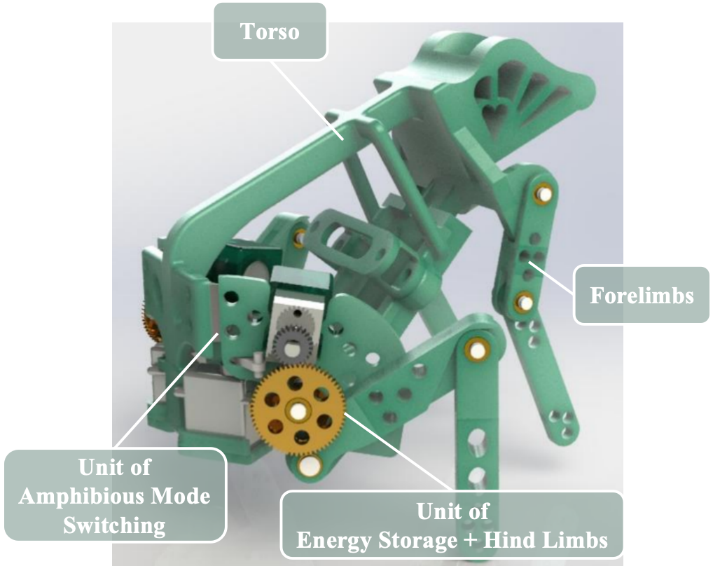
Figure 2.1: Architecture Overview
2.2 Torso and Forelimbs
The key components of the torso and forelimbs unit are detailed in Figure 2.2:
- 1 - Forelimb Joint: Torsion springs are placed on the shaft, with ends fixed in the holes of the upper and lower limbs to maintain posture and provide cushioning during jumps.
- 2 - Frog Head: For biomimetic decoration and adjustment of the center of gravity.
- 3 - Ventral Support Plate: Houses and secures electronic control elements.
- 4 - Back Panel Holes: For connecting with the hinge.
- 5 - Steering Gear Frame: Secures the steering gear in place.
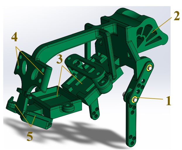
Figure 2.2: Components of Torso and Forelimbs
2.3 Energy Storage and Hind Limbs
The key components of the energy storage and hind limbs unit are shown in Figure 2.3:
- 1 - Motor: Fixed to the side panel via the motor mount.
- 2 - First Stage Gear: Axial and circumferential fixation on the motor shaft is achieved through interference fit and a D-shaped hole.
- 3 - Second Stage Gears and Cams: Engage with the first stage gear, with a split washer for axial fixation on a grooved shaft.
- 4 - Roller: Located at the back of the thigh to facilitate cam output.
- 5 - Thigh Shaft: Connects the thigh to the side panel, with a torsion spring fixed at one end in the side panel hole and the other end in the thigh hole.
- 6 - Thighs.
- 7 - Lower Leg: The lower hole allows for the torsion spring to pass through, connecting to the foot.
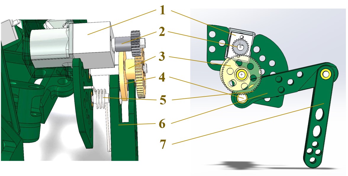
Figure 2.3: Components of Energy Storage and Hind Limbs
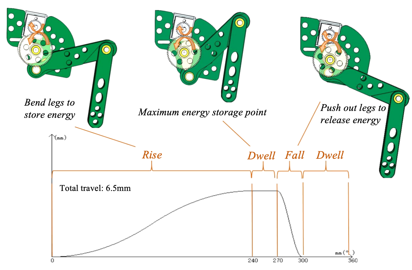
Figure 2.4: Principle of Energy Storage and Release
2.4 Amphibious Mode Switching
The key components of the amphibious mode switching unit are detailed in Figure 2.5:
- 1 - Hinge: Connects the torso and side plate.
- 2 - Slot: Allows the steering gear rocker arm to pass through.
- 3 - Steering Gear Rocker Arm: A unilateral arm that, when actuated, drives the side plate open or closed.
- 4 - Plug: Prevents the rocker arm from escaping the slot.
- 5 - Steering Gear.
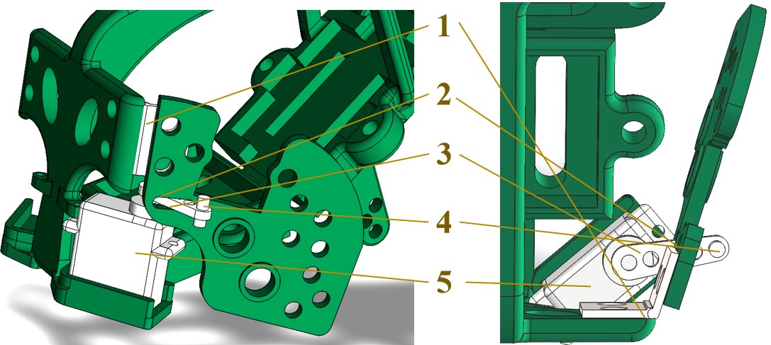
Figure 2.5: Components of Amphibious Mode Switching
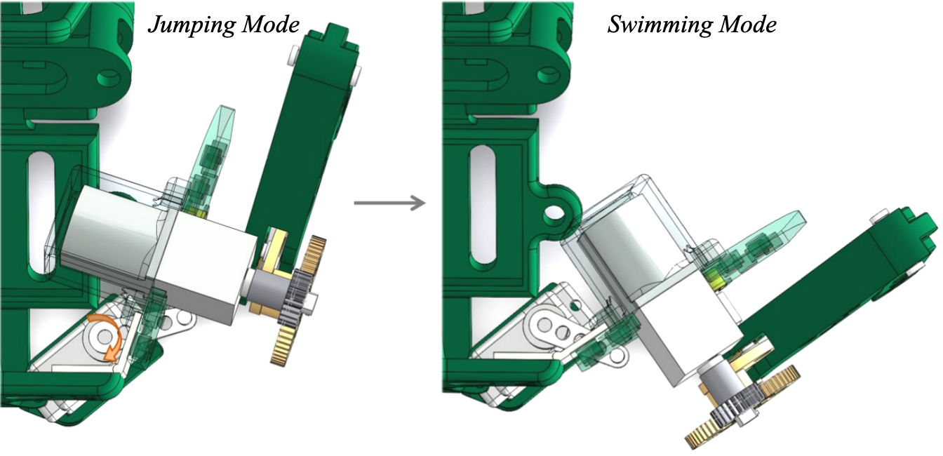
Figure 2.6: Principle of Amphibious Mode Switching
3. Calculations, Simulations and Overall Performance
Contributor: Yiqin Ma, Yuchen Yang, Hongyu Ji
3.1 Gear Design and Gear Strength Analysis
The gear set design parameters are as follows: primary gear m = 0.3mm, z = 24; secondary gear m = 0.3mm, z = 60. The transmission ratio is 2.5, with a center distance of 12.6mm. The strength analysis of the gear set is provided below:
\(\sigma _ {H2} \leq \sigma _ {H1}\)
\(\sigma _ {H1} = Z_ {E} Z_ {H}\sqrt {\frac {2KT_ {1}(u\pm 1)}{bd_ {1}^ {n}}} =2.5 \times 143.7 \sqrt {\frac {2\times 1.1\times 15\times (60\div 24+1)\times 9.8}{0.7\times (0.3\times 24)^ {3}\times 60\div 24}} =472.9MPa\)
\(\sigma _ {H\lim } =800MPa,[ \sigma _ {H} ]= \frac {\sigma _ {H\lim }}{S_ {H}} = \frac {800}{1.5} =533.3MPa \)
\(\sigma _ {F1} = \frac {2KT_ {1}Y_ {FYS}}{bm^ {2}z_ {1}} = \frac {2\times 1.1\times 15\times 9.8\times 2.65\times 1.58}{0.7\times 7.2\times 0.3^ {2}\times 24} =124.4MPa \)
\(\sigma _ {F2} = \frac {2KT_ {1}Y_ {FYS}}{bm^ {2}z_ {2}} = \frac {2\times 1.1\times 7.2\times 0.3^ {2}\times 15\times 9.8\times 2.28\times 1.73}{0.7\times 18\times 0.3^ {2}\times 60} =18.7MPa\)
\(\sigma _ {F\lim } =300MPa, S_ {F} =2.0,[ \sigma _ {F} ]= \frac {\sigma _ {F\lim }}{S_ {F}} =150MPa\)
\([ \sigma _ {F} ] \geqslant \sigma _ {F},[ \sigma _ {H} ] \geqslant \sigma _ {H}\)
\(\Rightarrow Safe.\)
3.2 Motion Simulation
The simulation of the retraction and extension of the rear leg is achieved by setting a motor to the first stage gear. The jumping motion simulation includes this motor, ground contact, gravity, and the torque between the two side plates and the back legs.
3.3 Rendering
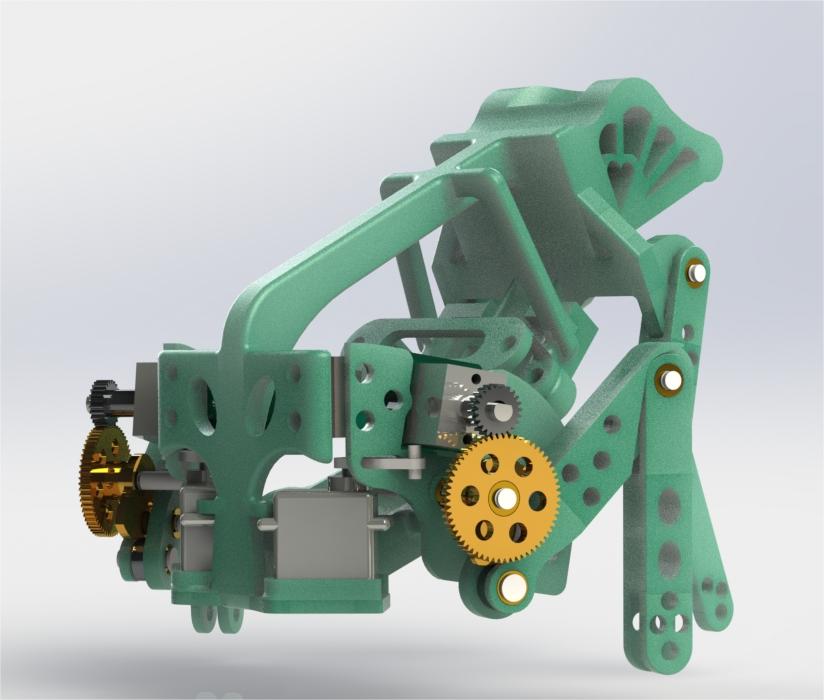
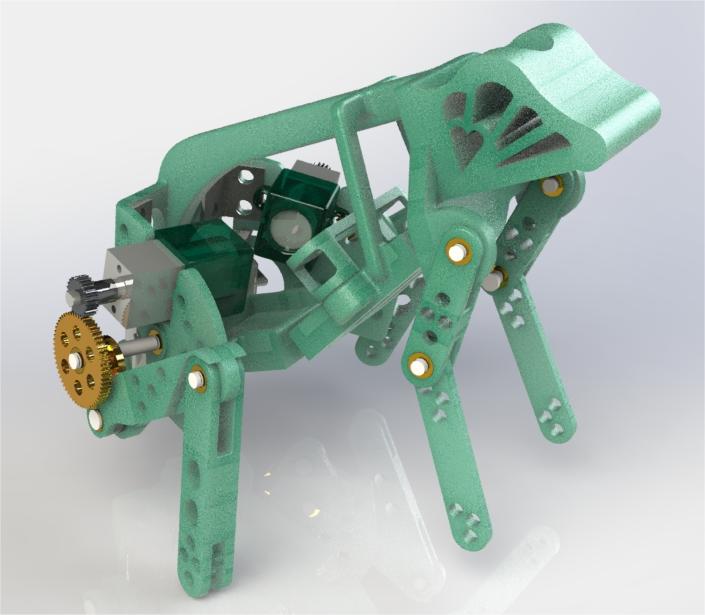
Figure 3.1: Rendering
3.4 Exploded Views
4 Circuits and Programs
Contributor: Xingyao He, Hongyu Ji
4.1 Module Selection
For the final design solution, we selected the following components:
- N20 Motor (6V, 50r/min): Capable of providing a torque of 1.5 kg-cm.
- SG90 Servo: Lightweight and small size to meet project requirements.
- 401025 Polymer Lithium-Ion Battery: Dimensions 25mm x 10mm x 4mm, 3.7V supply voltage, 100mAh capacity.
- HC05 Bluetooth Module: For stable signal transmission between the development board and cell phone.
- Arduino Nano Development Board: As a microcontroller control unit.
4.2 Circuit Layout
The prototype’s circuit layout, which includes the jump function, is detailed in the following chapter. The amphibious mode conversion design was not included in the final circuit, hence the absence of the SG90 servo (Figure 4.1).
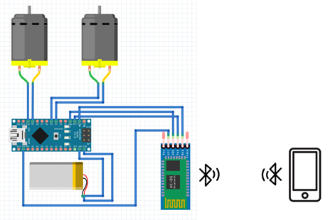
Figure 4.1: Circuit Layout
4.3 Programs
The control functions include:
- actuate(): Triggers synchronous rotation of both motors for a calculated duration to ensure the energy storage mechanism reaches the trigger point upon completion.
- l_clockwise(): Manually controls the left motor to rotate clockwise to adjust the robot’s attitude.
- l_counterclockwise(): Manually controls the left motor to rotate counterclockwise for attitude adjustment.
- r_clockwise(): Manually controls the right motor to rotate clockwise for attitude adjustment.
- r_counterclockwise(): Manually controls the right motor to rotate counterclockwise, used for adjusting the robot’s attitude.
- self_adjust(): Synchronizes both motors for a set duration to adjust the robot’s attitude during landing.
- set_fine_tune_true(): Activates fine-tuning mode.
- set_fine_tune_false(): Deactivates fine-tuning mode.
5. Prototyping and Test
Contributor: All group members
5.1 Prototype
We constructed a prototype for continuity and jump force testing (Figure 5.1).
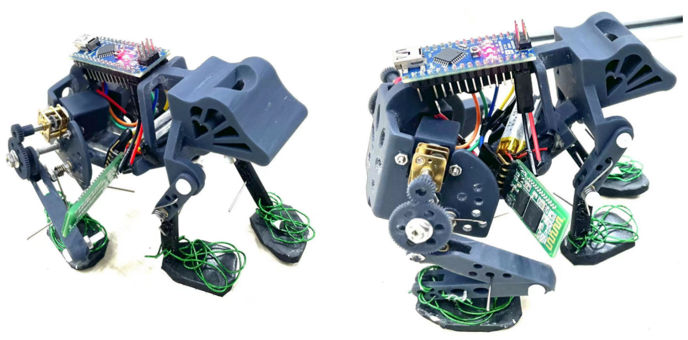
Figure 5.1: Prototype
5.2 Prototype Test
The continuity test demonstrated that the leg’s motion trajectory meets our expectations, achieving continuous motion. However, the jump force test did not yield the desired results, with the robot failing to jump. We attribute this to: (1) the high density of 3D printing materials, resulting in a heavier overall weight; (2) the torsion spring’s insufficient torque for jumping; (3) the “cantilever beam” issue due to one-end fixation of the shaft, causing leg skew and suboptimal torsion spring performance.