1. MuJoCo Simulation Environment
Built on the MuJoCo platform, I have created a simulation environment for a human-shaped dual-arm robot that encompasses three distinct task scenarios. The environment incorporates over 40 different item models and over 70 diverse textures. Each item and environmental element is accompanied by a model file and the corresponding MJCF configuration file.
1.1 Three Task Scenarios
1. Desk Grasp: This scenario simulates the task of grasping items on a desktop. The environment includes a variety of foods, fruits, and common daily items (Figure 1.1a).
2. Shelf Grasp: Designed to simulate the process of grabbing items from a shelf, this environment features various items such as beverage bottles, cans, and boxes. The complexity of this environment is intended to test the robot’s recognition and grasping capabilities (Figure 1.1b).
3. Pick and Place: In this setup, multiple bins are used to test both grasping and placing actions. The robot must not only recognize and grasp an item but also place it in a specific location (Figure 1.1c).
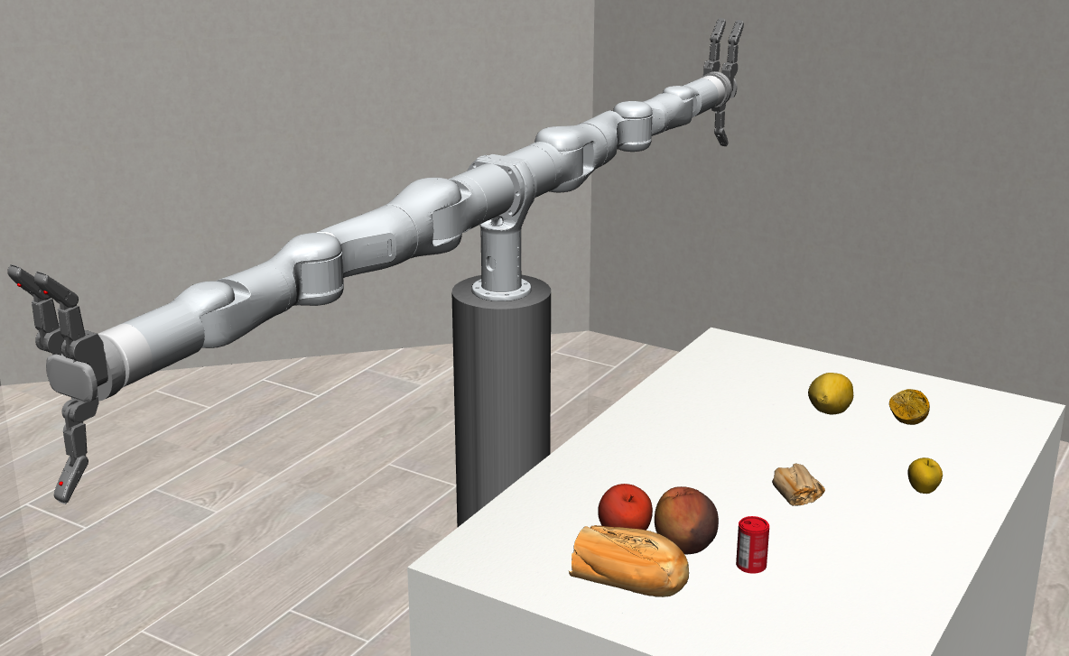
(a)
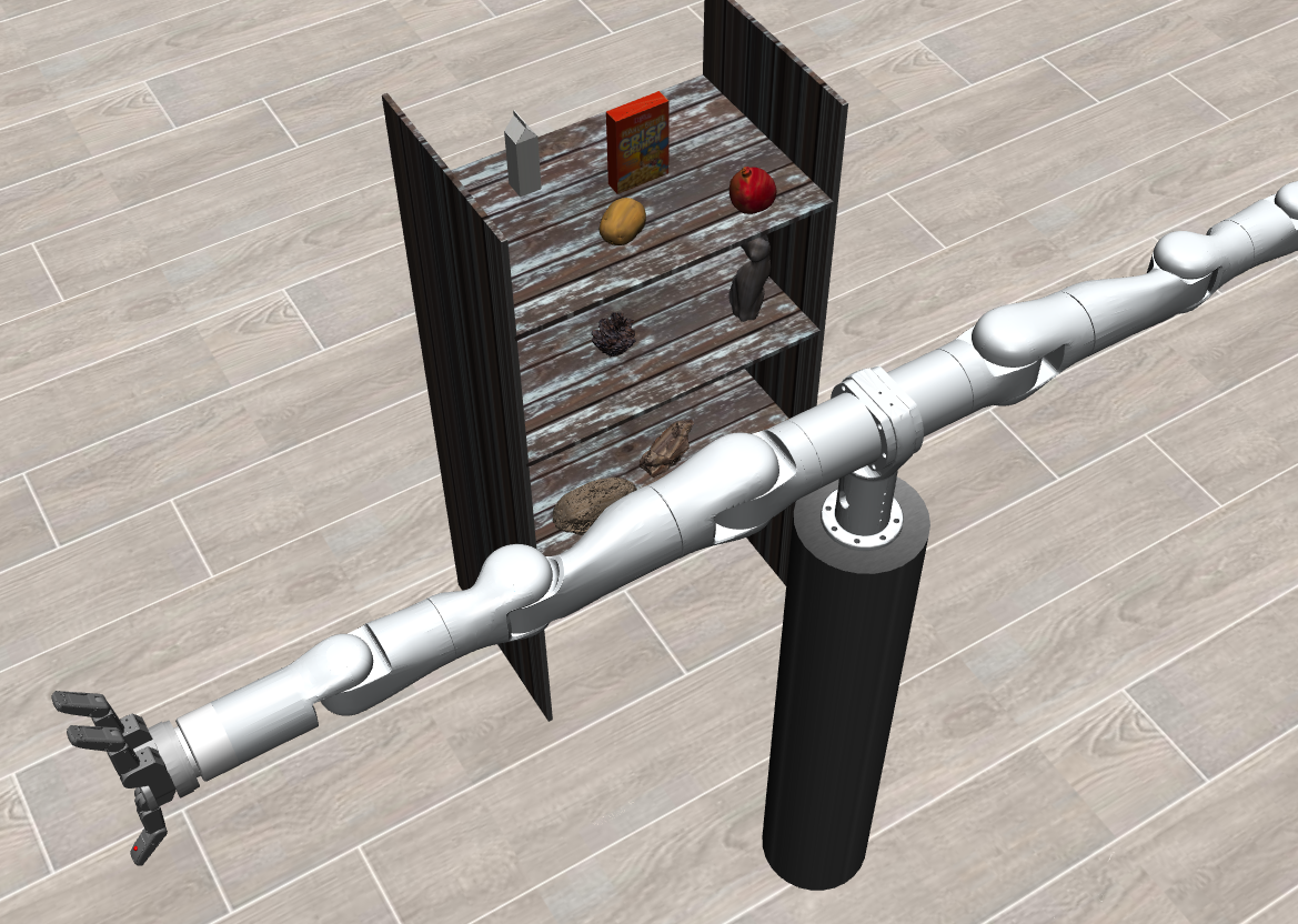
(b)
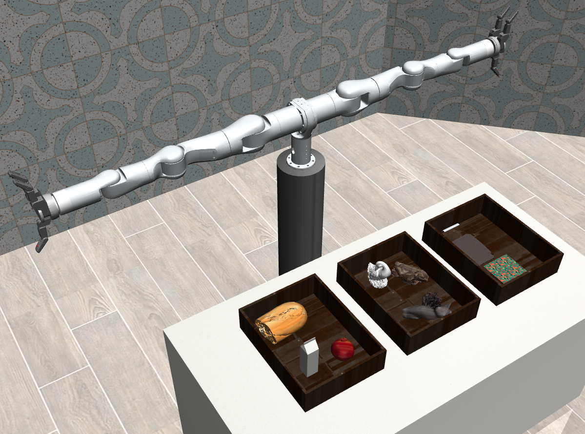
(c)
Figure 1.1: Task Environment
(a) Desk Grasp
(b) Shelf Grasp
(c) Pick and Place
2. Demonstration Collection Pipeline
2.1 Overall Pipeline
The standard process for collecting presentation data is facilitated by a data glove (Figure 2.1). This glove serves as an interactive medium between the operator and the robot, equipped with an array of sensors. It includes four sensors that capture the spatial position of the arm (providing quaternions) and seven sensors that measure finger angles (providing angle values). After calculating these quaternions and angle data, the corresponding angular motion sequence of the robot’s joints is transmitted in real time to the simulation environment, enabling precise motion control. During the robot’s task execution, data is collected at set intervals; joint angle values are stored in the qpos.hdf5 file, and the RGBD camera’s image data is stored in the RGBD.hdf5 file.
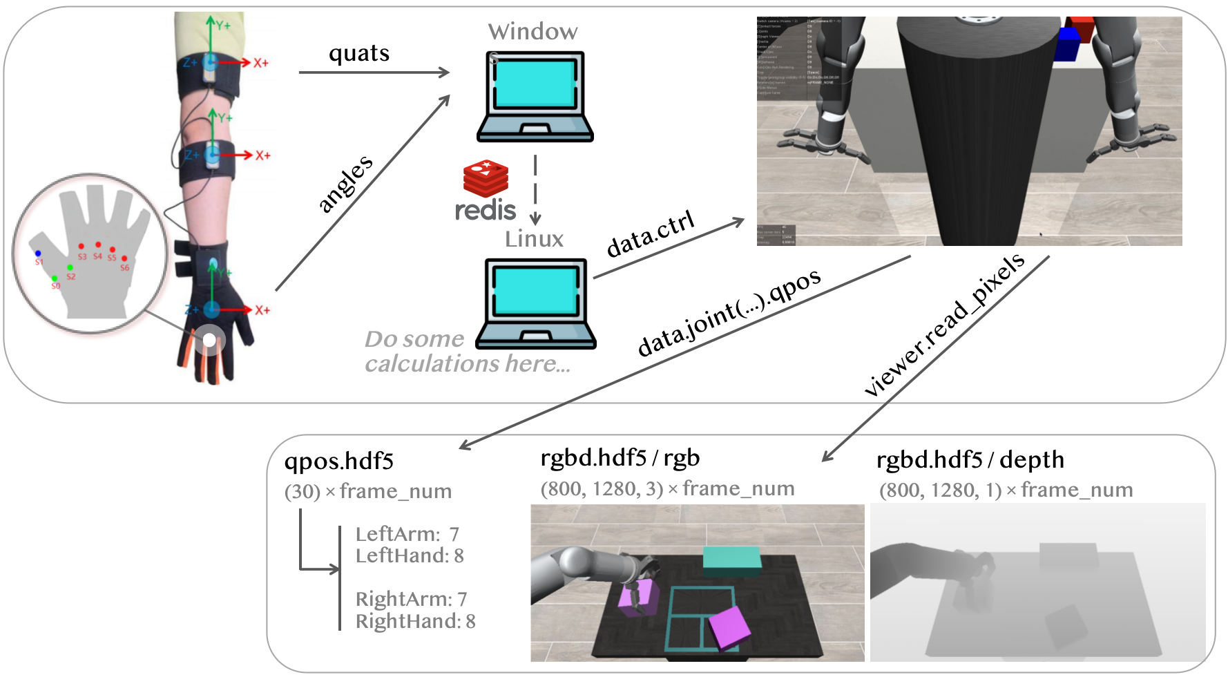
Figure 2.1: Demonstration Collection Pipeline
2.2 Arm Motion Mapping
1. Calculate the Relative Rotation Matrix
Each sensor establishes a coordinate system, and the relative rotations between these systems need to be determined.
$$ \begin{align} ^{Fore}R_{Hand} &= ^{0}R_{Fore}^T\cdot^{0}R_{Hand} = quat2rot(quatFore)^{T} \cdot quat2rot(quatHand) \\ ^{Upper}R_{Fore} &= ^{0}R_{Upper}^T\cdot^{0}R_{Fore} = quat2rot(quatUpper)^T \cdot quat2rot(quatFore) \\ ^{Body}R_{Upper} &= ^{0}R_{Body}^T\cdot^{0}R_{Upper} =quat2rot(quatBody)^T \cdot quat2rot(quatUpper) \\ \end{align} $$
2. Calculate Changes Over Time
The change in the relative rotation matrix of adjacent sensors must be calculated with respect to the initial time. This quantifies how the relative rotation matrix at the current time point \(t\) differs from that at the initial time point \(t_0\). $$ \begin{align} ^{Fore}R_{Hand}^{t_0 \rightarrow t} &= (^{Fore}R_{Hand}^{t_0})^T\cdot ^{Fore}R_{Hand}^{t}\\ ^{Upper}R_{Fore}^{t_0\rightarrow t} &= (^{Upper}R_{Fore}^{t_0})^T\cdot ^{Upper}R_{Fore}^{t}\\ ^{Body}R_{Upper}^{t_0\rightarrow t} &= (^{Body}R_{Upper}^{t_0})^T\cdot^{Body}R_{Upper}^{t}\\ \end{align} $$
3. Convert to Euler Angles
The rotation matrix is converted into Euler angles, and a selected angle is multiplied by the corresponding coefficient to adjust for the robot’s motion capabilities.
$$ \begin{align} {\color{Gray} For\ joint\ i:}&\\ ArmPos[i] & = initArmPos[i]\pm ArmRateR[i]\cdot Rot2euler({\color{Peach} *} )[{\color{Violet} n } ]\\ {\color{Gray} in\ which:}\ & {\color{Peach} *} \ {\color{Gray} is\ ^{Fore}R_{Hand}^{t_0 \rightarrow t}\ or\ ^{Upper}R_{Fore}^{t_0\rightarrow t}\ or\ ^{Body}R_{Upper}^{t_0\rightarrow t}}\\ & {\color{Violet} n} \ {\color{Gray} is\ 0/1/2 } \end{align} $$
2.3 Hand Motion Mapping
Given the configuration of the three-finger dexterous hand and the constraints of sensor data, a unique and efficient hand mapping method has been devised. On the data glove, the joints of the thumb, index finger, and middle finger can be directly mapped to their corresponding joints on the dexterous hand. The floating joint is managed by angle sensors in the ring and pinky fingers. As there are no angle sensors for the three joints of the dexterous hand, a force feedback-based control method is utilized. In the simulation environment, when the tactile sensor detects contact between the fingertip and an object that exceeds a certain force threshold, the system adjusts the joint angle, simulating the bending action of the finger until the contact force reaches a preset maximum (Figure 2.2).
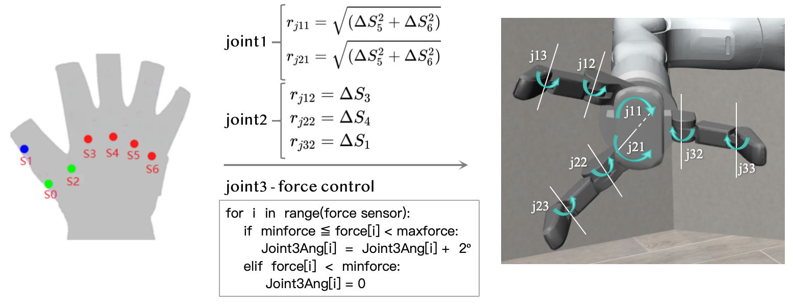
Figure 2.2: Hand Motion Mapping
An example of the robot control in the simulation process is demonstrated in the video below.
2.4 Stacking Task
The stacking task challenges the robot to grasp items and place them with precision according to the shape of the stacking area. To simulate complex stacking tasks, a flexible and customizable stack generation function has been designed. It automatically creates stack areas and corresponding square workpieces based on preset parameters, such as stack length, width, height, structure, and arrangement (Figure 2.3). The positions of items and stacks are randomly generated, ensuring a variety of stacking scenarios.
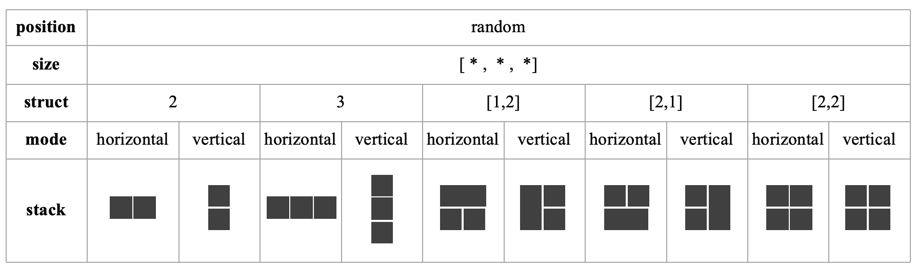
Figure 2.3: Stack Generation
An example of an RGB video reconstruction from the camera for the stacking task is presented below.